2P Innovation Pty Ltd
Circuit board design, microwave RF, and embedded systems. Adelaide, South Australia.
I'm Andrew - RF/embedded engineer by day, trouble-maker after hours, and the beautiful face behind the 2P logo1. I work out of a state-of-the-art garage: RF test gear and automated assembly tools acquired over the years and across projects. What follows is previous work and the lessons learnt along the way. I figure that explains what I can do better than a list of capabilities would, and when you email about any of it you get the person who drew the schematic, not a ticket number.
Selected work
Charging bar and RF tokens
Telstra
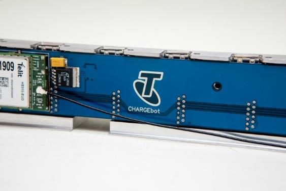
In 2015 Telstra needed a way to charge customers' devices at trade shows, and to tell them when the charge was finished. The charger itself was off the shelf and stayed that way - the job was to work out what it was doing. We built a charge sniffer that watches the charging lines, and wrote the algorithms that turn that into a state of charge and a dependable finished report sent back to a server over the cellular module.
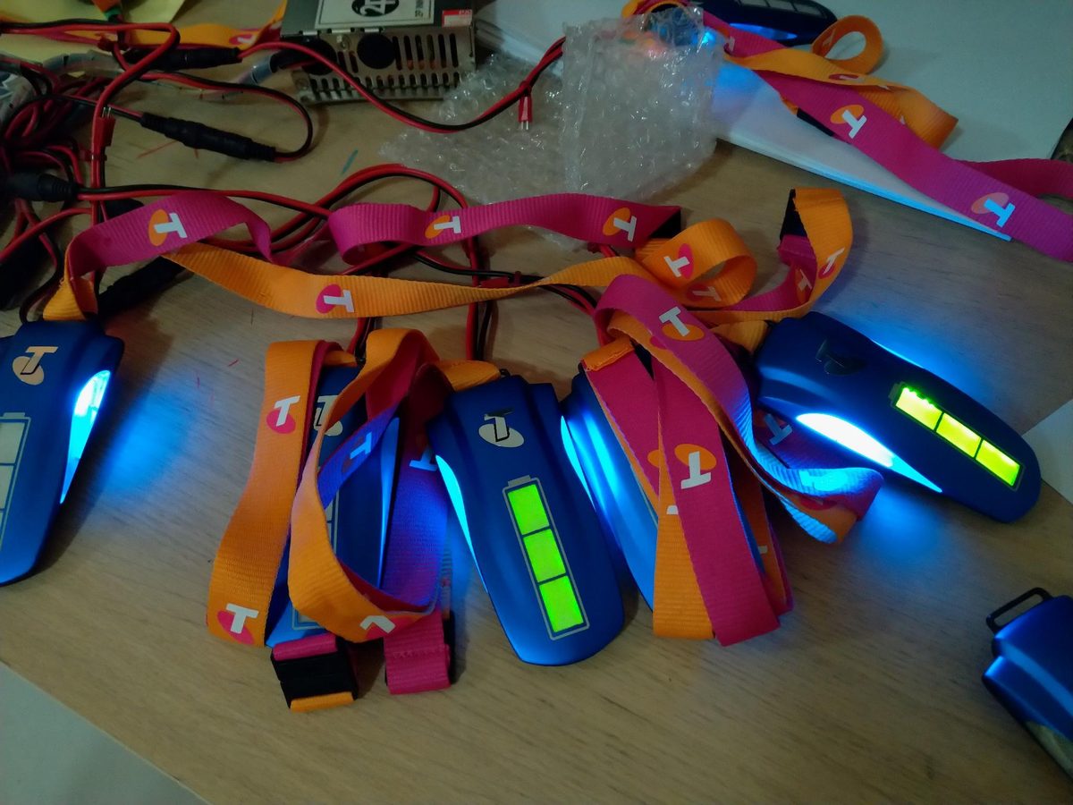
Having delivered that, Telstra asked whether we could do the pagers as well - the tokens in that photograph, and that's what the server notifies. We designed the enclosure, the electronics and the software, and delivered 20 units. They still work today.
(We, here, because 2P was a partnership at the time.) Small things worn on a lanyard, handled by people who will never once think about them, and made in quantity: a completely different set of problems from the first job, for the same customer.
RFID reader for the Art Gallery Society of NSW
Art Gallery Society of NSW
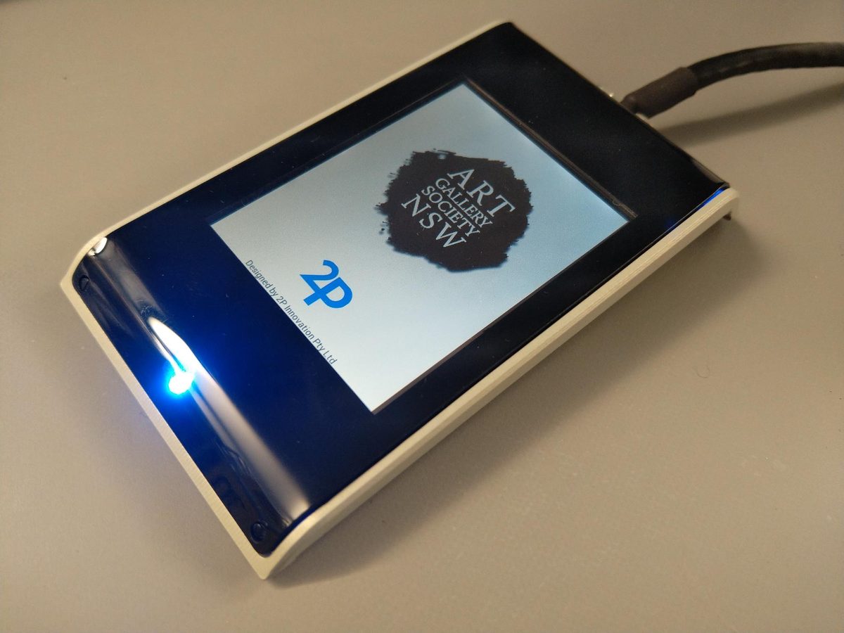
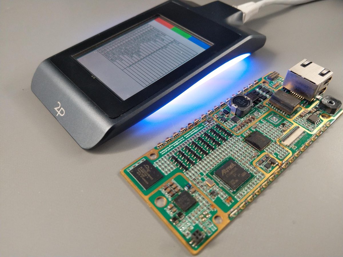
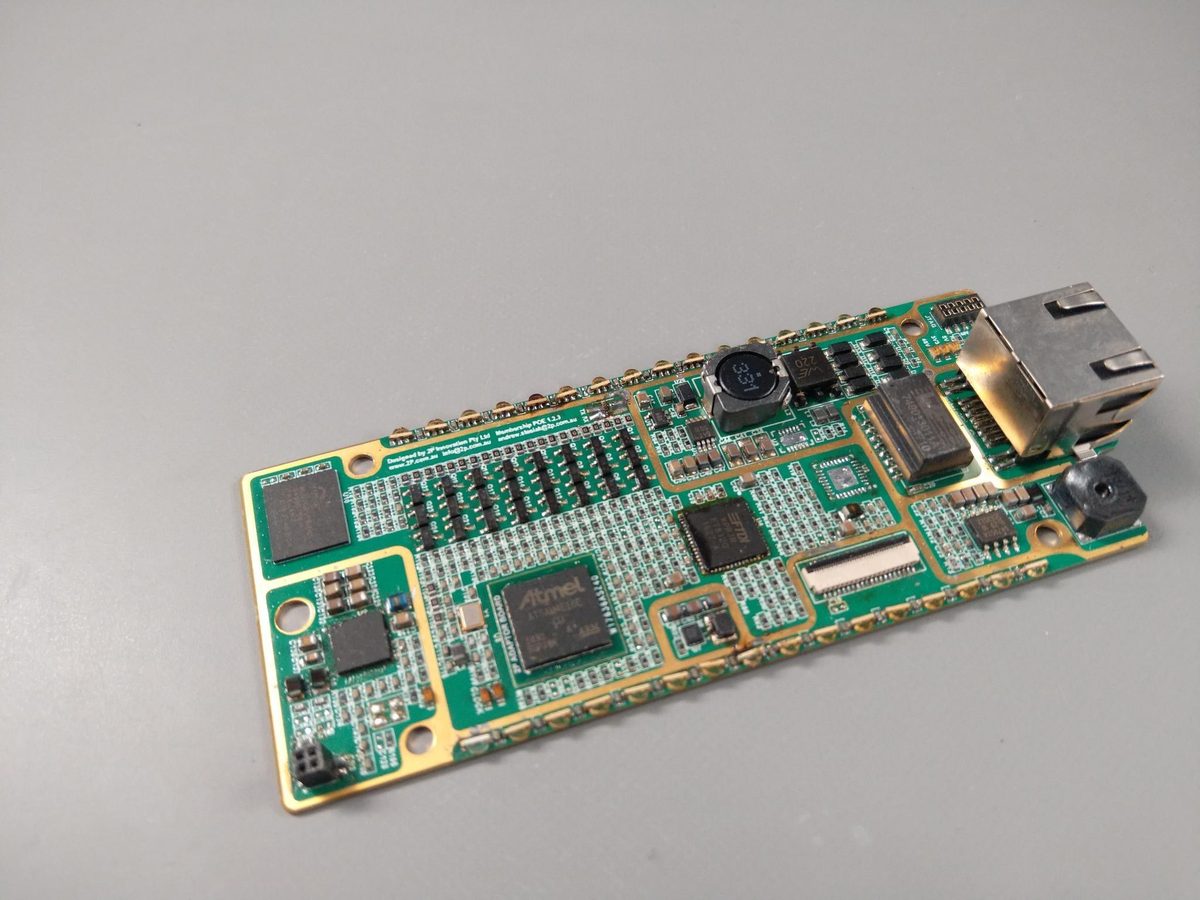
The Society's membership cards carry no date printed on them, so there was no way for staff to check one by eye. What they needed was a reader that looked right in an art gallery, was minimally intrusive (a single cable, Power over Ethernet), could be mounted in any of several configurations with its indicators visible from most directions, and talked directly to their internal system. Surprisingly, nothing off the shelf did that, so they came to us.
Board, firmware and enclosure, built in 2015. The case is aluminium, which both shields and detunes the antenna - nothing an impedance transforming network couldn't fix, once it was designed against the antenna as it actually behaves inside the case, not as the datasheet draws it. Small runs of a thing like this are exactly the job a big manufacturer doesn't want and a hobby build can't survive: it has to be finished enough to hand to staff who have no interest in electronics.
Modular precision power supply
University of Adelaide - Portable Atomic Clocks (PACS)
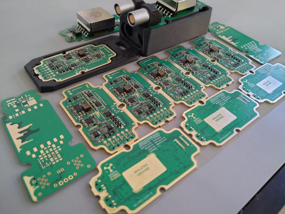
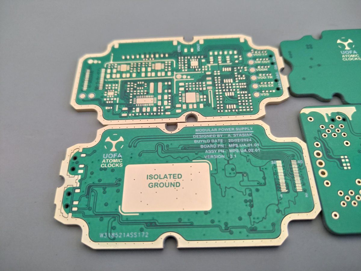
This one isn't 2P work. I designed it during my sojourn at the University of Adelaide, employed on the Portable Atomic Clocks (PACS) programme. It is here because this site is about me at least as much as it is about the company.
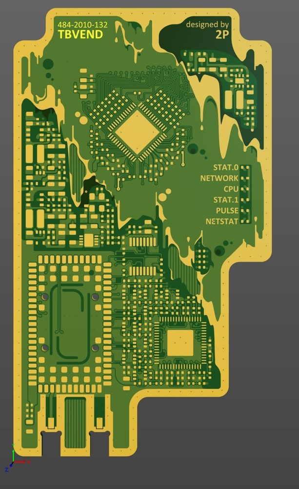
The clocks needed a range of supplies with precision outputs in various configurations: some voltage regulators, some current sources. The common thread was isolation, precision and modulation. Ground loops are a bad idea when analogue signals bridge devices on separate supplies, and that's what the large region marked isolated ground on that silkscreen is about. That's not documentation - it's the design. Split it wrong and the noise you were keeping out arrives by another route, and on a clock, noise on the supply becomes noise on the thing you're using to measure time.
From experience in similar environments I knew the specification would change as a blue-sky design like this one progressed. So I made it modular and configurable within a fixed form factor: the team could commit to the mechanical design and the routing of the full system, knowing the supply could be reconfigured internally if things moved.
LiDAR analogue front-end
Spiral Blue
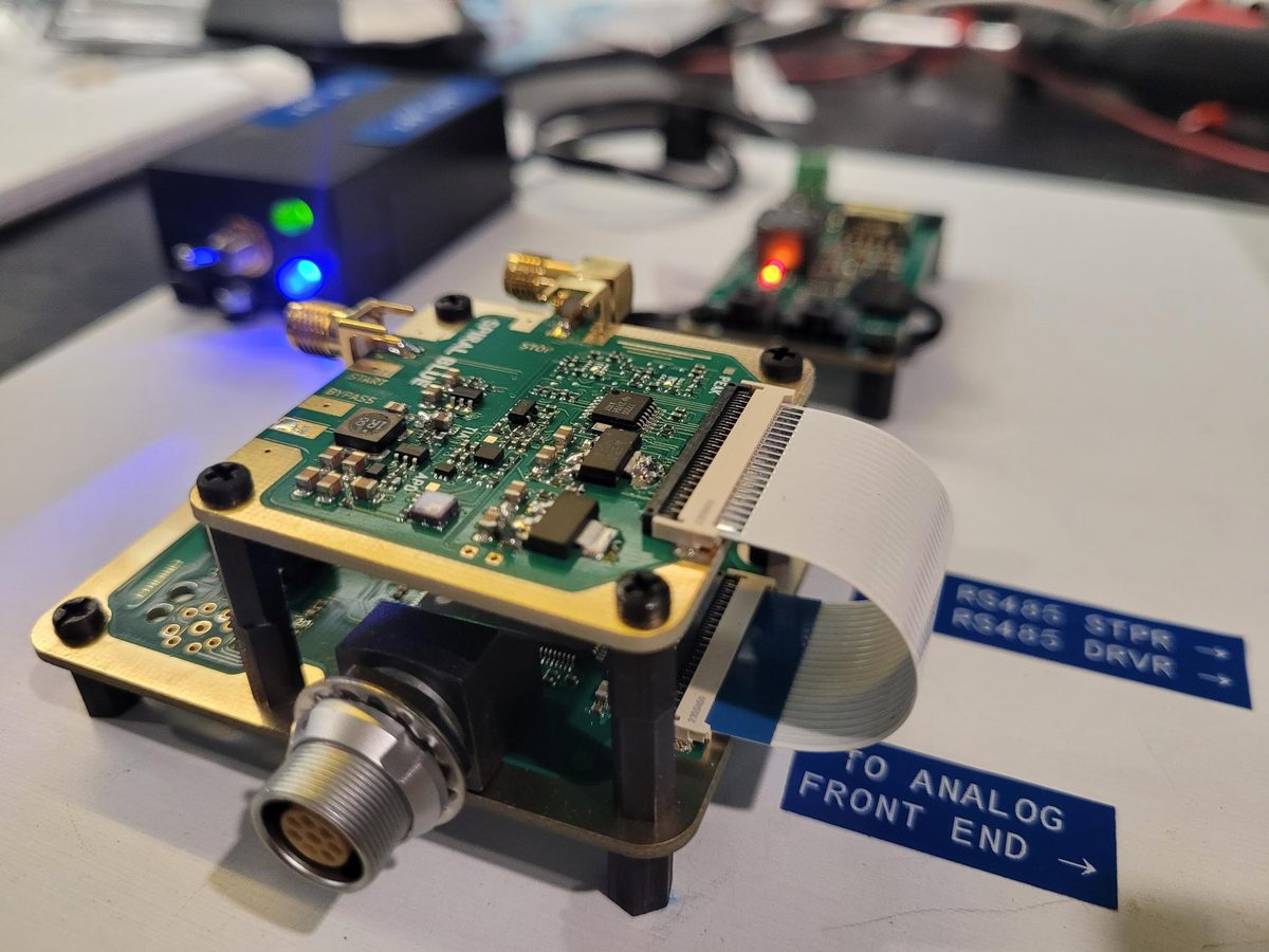
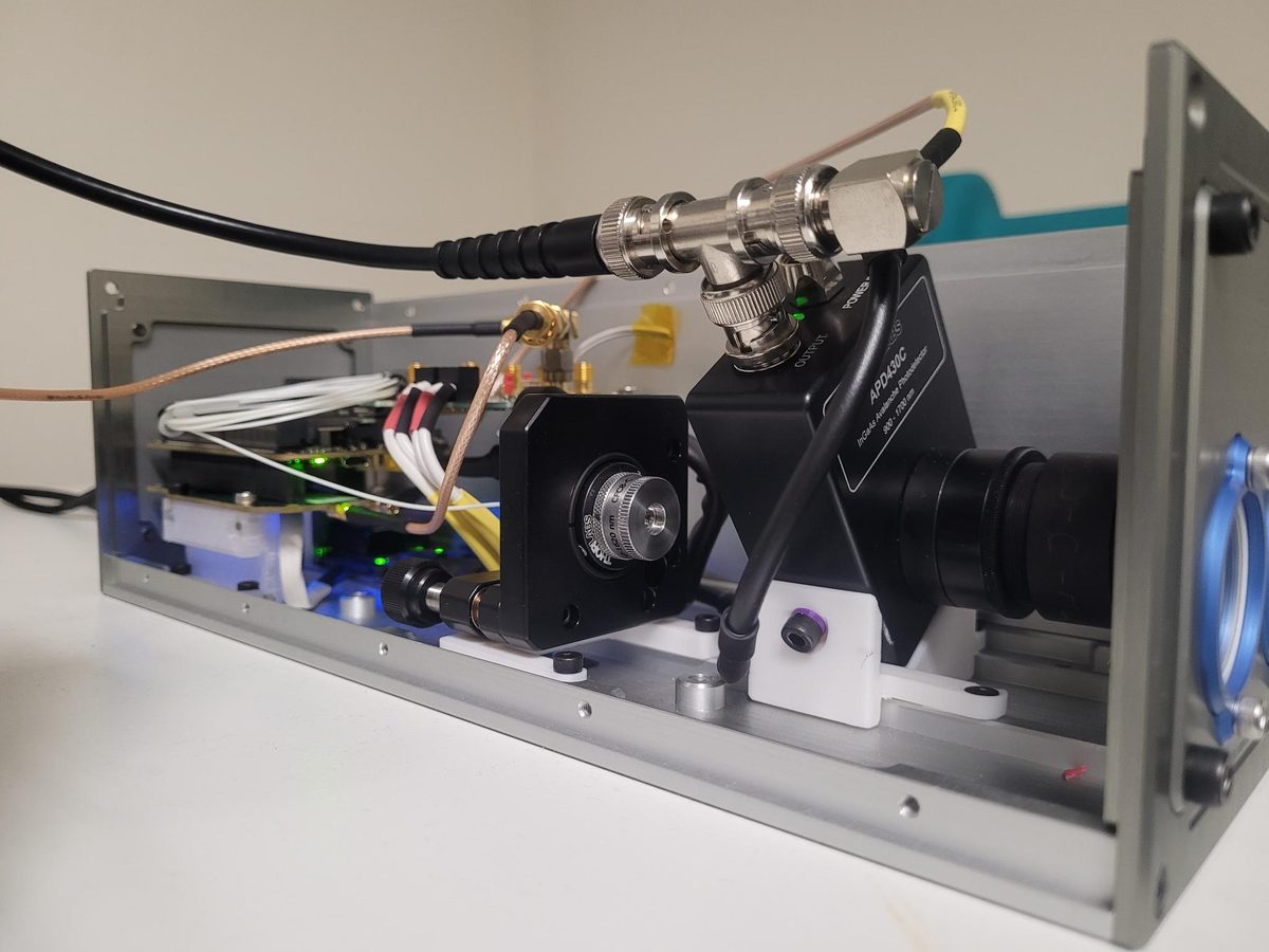
A prototype 3U LiDAR, from the ground up, in four weeks. This one went down to the wire - the bench was literally left in a ready-to-ship state less than an hour from the hard deadline. Late nights, caffeine and a supportive team made it possible; particular thanks to Spiral Blue's engineering team.
The analogue path is where a LiDAR's performance is won or lost. The return signal is small, fast and buried in noise, so grounding, shielding and supply isolation stop being style questions and become the specification. This one also had to live inside an optical assembly, which adds a constraint: the electronics fit around the optics, not the other way round.
Microwave filters and triplexers, in volume
Black Art Technologies
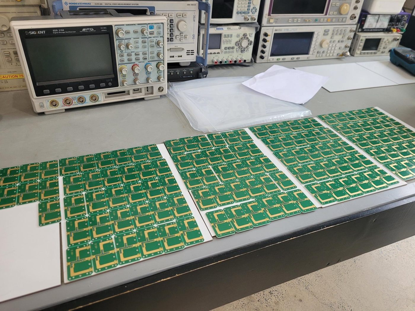
This is the work the rest of the site is really about. Distributed-element microwave filters are unforgiving: the passband is set by gaps and lengths measured in tenths of a millimetre, and if the synthesis is wrong you find out after you've paid for the boards. I synthesise them from first principles, check them against full-wave electromagnetic simulation, and measure the result on a vector network analyser before anyone commits to a run.
Assembling these taught me that RF assembly is less forgiving, and needs more care, than most. More solder, more stubs, more noise. Residual flux affects the impedance, and you'll see it on the S-parameter plot.
The synthesis engine I use for this is now free for anyone to use.
An RF front-end, and the base station built to test it
Client not named
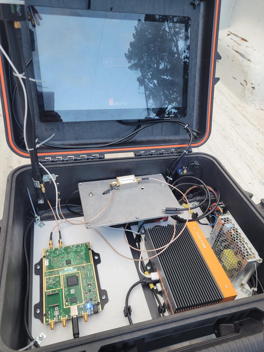
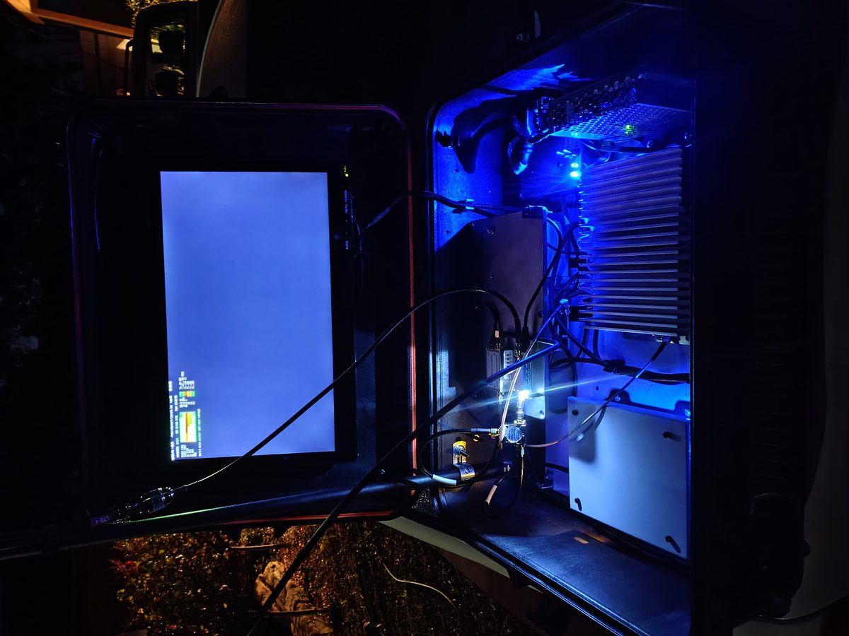
The task was an RF front-end to improve performance in a built environment - a metric you can only partly measure from my sophisticated automotive bedroom. Real-world performance data is more useful and more compelling, and that needs a base station, so I built one: a Pelican case you can plant on a bench and be a telco with for a respectable distance. At legal power, and with a healthy respect for the ACMA.
Anything that leaves the bench also has to survive being carried, dropped, rained on and powered from whatever is available. That constraint shapes the board far more than the block diagram does.
Rugged personal locator
Client not named
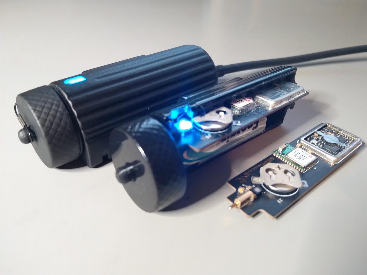
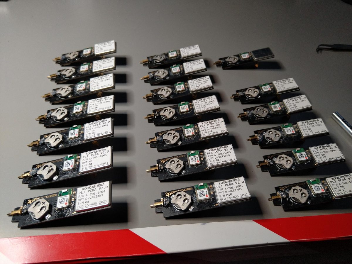
An interim capability: adding position and location features to legacy portable radios - ahead of the replacement upgrades being commissioned. The functionality was relatively simple. The core requirement was robustness, and in particular antenna reception across every mounting position the unit might end up in. For a small form factor, with limited ground plane area and a large detuning element (the human body) right next to it, that's not as simple as one might expect.
Photonics instrumentation
University of Sydney
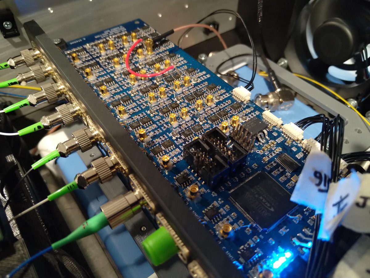
A research-grade, high-bandwidth, real-time spectrum analyser. The Fourier transform was elegantly performed in fibre, with multiple outputs in the RF domain to be captured and processed into something meaningful.
Many identical channels on one board, which sounds easy and isn't: the channels have to match each other, and every one is a chance for crosstalk and for a supply to sag differently from its neighbour. Research hardware also has to be honest about its own limits, because somebody's going to publish numbers that came out of it.
One of the most exciting projects I've ever worked on. Thanks to the team at the University of Sydney for the privilege.
Dive computer
Startup, no longer trading
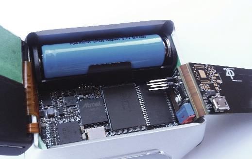
A compact dive computer, the core requirement being to stay dry and functional hundreds of metres below the surface. An early project: the mechanical side was far more complicated than I expected, and it was the first flex-rigid I designed for a client. The company never took off, but the hardware was enjoyable to work on, and the lessons about material corrosion and seal-failure modes under pressure are still with me.
Maybe I should build attack submarines?
My ethos
When I was a young lad still in school, a distinguished and respected quality consultant who lived on my street told me the story of how he once improved a metal fabricator's quality problems by forcing every welder and every machinist to put their signature on their work (probably not physically). The idea was to make them take ownership of it, and it was an immediate success. If what you produce is seen by the world and judged, your reputation on the line, the incentive to produce only your best every time is a natural one. I never forgot what that meant, and it's why I put my name on everything I do.
My name is on the silkscreen of most of the boards on this page. That's not sentimentality. It's why I'd rather remake a board at my own cost than ship one I'm not happy with, and why I'm still answering questions about designs I finished years ago.
So, jokes aside: I like to think I'm good at what I do because I care as much about how it affects me as about how it affects you. I make mistakes like everyone else and I own them when they arise. That's not just honest, it's also the best way to improve.
I started this with nothing in 2015, continuously reinvested to meet project needs. Some people buy houses but I bought a top-end spectrum analyser instead.
If you arrive with a volume job I'll scale up to meet it, not turn it away. What I won't do is take on work I can't do properly, or give you a number I already know is optimistic. I'll tell you before you spend money that the gap your filter needs is finer than a standard PCB process can etch - that's the sort of thing that costs me a job now and again, and it's still the right way round.
The garage
A well-maintained garage can be an effective lab, and I've made good use of mine over the past 10+ years. The pick-and-place has been essential for optimisation and rapid development - for a small workshop like this, it's quite unusual. The RF gear lets me validate designs before they ship, and the view of the hills reminds me how lucky I am.
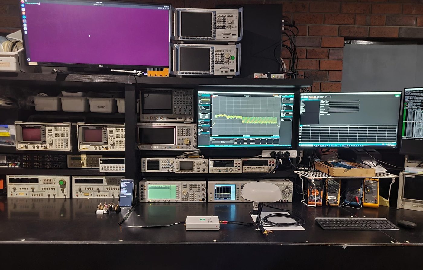
The reason the garage matters is that it's the difference between believing a design works and knowing it does. A microwave filter that simulates beautifully and measures 200 MHz low is a common experience - the only way to find out which one you have is to build it and put it on an analyser.
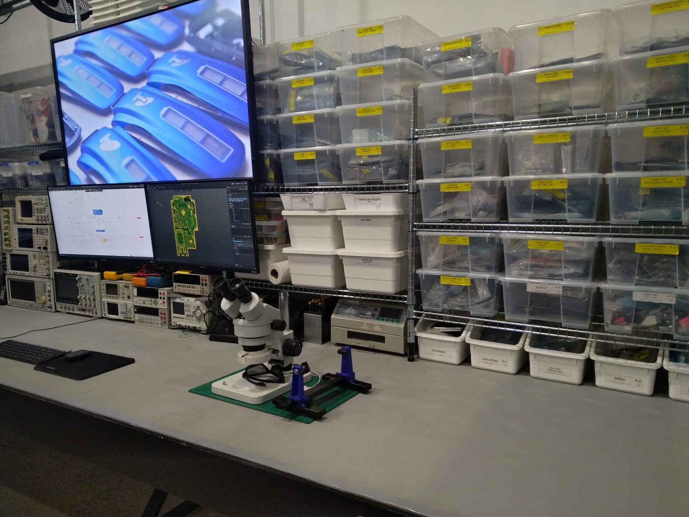
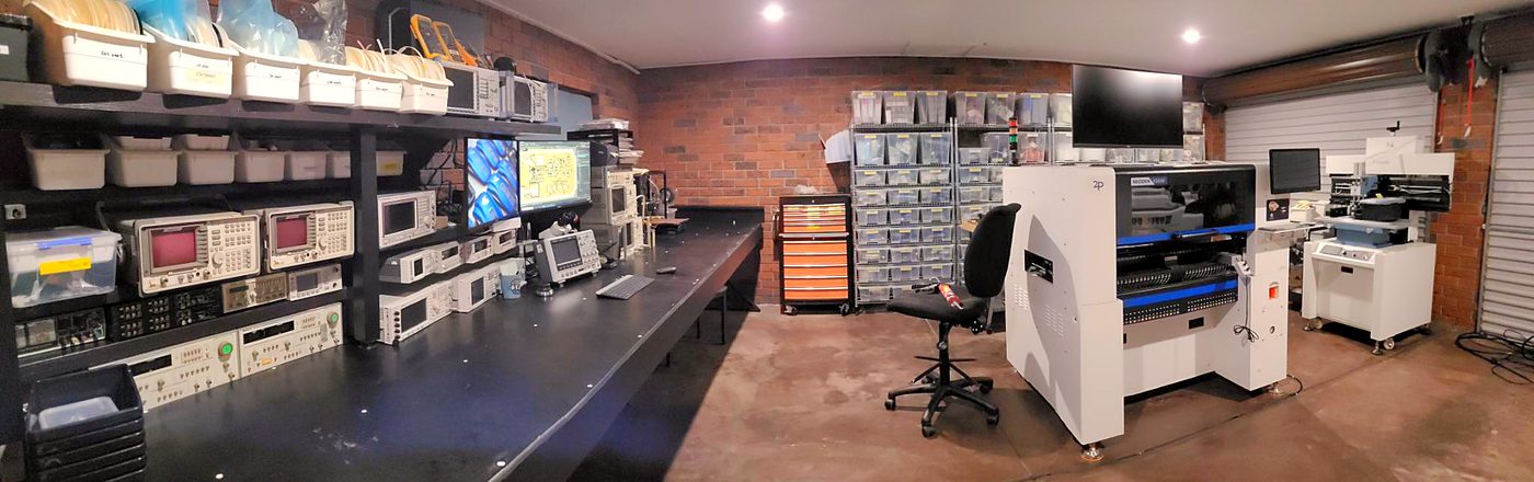
Assembly happens here too - the part most smaller outfits have to send away. Prototypes and small runs go through the pick-and-place, the stencil printer and the reflow oven in the corner of that photograph; larger RF runs go to RF Shop, who have the volume capability and the experience with microwave laminates that I don't pretend to match.
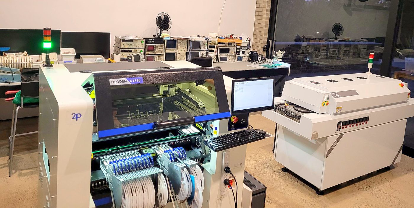
If I quote a measurement on this page, it came from this equipment.
Free tools
Over the years, I've built several RF tools to quickly produce distributed-element geometries - quick, theory-based synthesis good enough to take into simulation and optimise. I've put them online for everyone to use, and feedback is always welcome. They grow whenever a new project needs a feature they lack, so consider them a perpetual work-in-progress.
Contact
If any of the above demonstrates a capability you need, I'd like to hear from you. I'm aware that understanding someone's needs takes more than an hour, so I don't charge preliminary consultation fees. If what you need is beyond my scope I'll tell you early and save us both the time - generally speaking, anything with electronics, mechanical, RF or embedded design or assembly is worth reaching out about.
Email is best. Tell me what you're trying to build and roughly how many, and I'll tell you honestly whether I'm the right person for it.
| engineering@2p.com.au | |
| Company | 2P Innovation Pty Ltd |
| ABN | 76 602 895 769 |
| Post | PO Box 544, Mitcham Shopping Centre, SA 5062, Australia |
| Client portal | portal.2p.com.au |
1. 2P Innovation began as a partnership, which is why some of the entries above say we, and when a job is big enough to need more than one person I still bring people in. Day to day, and for a long time now, it is me.